Add a Dodge Tigear-2 Reducer or a Baldor Motor to get free shipping on your entire order!
NORD Gear Constant Speed Drive Selection Guide

At Power Motion & Industrial Supplies, we are a proud distributor of NORD Gear’s full product line. On our E-Commerce platform, we currently only list the FLEXBLOC® Worm Gear product line for sale. Due to their modularity, it is easy to select the components to assemble your own gearmotor that best suit your needs. The rest of the product lines are made-to-order, with millions of possible configurations, so it is best to work with a knowledgeable distributor to help configure the perfect gearmotor for your application. For that reason, we have developed this guide to help you gather all the information you need to provide us in order to start that process.
The First Question: Are you looking for a replacement to an existing gearmotor?
If the answer is yes, then this process should be very simple! All we will need is the serial number from the nameplate on the gearbox housing. If it is a modern US serial number (ex. 201360663-100) we can look up every detail of your unit and provide you a replacement quote very quickly. If it's in a different format, we will have to send it in to NORD customer service to look it up for us, which could take a day or two. If you want the replacement to be the same as the original, then that is all we need! If you want to make modifications to the replacement, keep reading to see what your options are.
New Applications: How to Choose a Brand New Gearmotor
If you answered NO to “The First Question”, then we will need some information from you to determine the right gearmotor for your application. Below is a summary of the questions that will need to be answered, followed by a more detailed explanation of each. And if you need any help determining any of these answers, we are always happy to assist you! Just give us a call at (833) 664-1523 or email us at info@pmisupplies.com.
1) Output speed or gear ratio
2) Horsepower or output torque
3) Desired service factor
4) Gearbox type
5) Gearbox input
6) Mounting position
7) Output Shaft Type and Size
8) Options
9) Checks
1) What is your desired output speed/gear ratio? The first step is determining the final output speed you need. This is usually described in revolutions per minute (RPM’s) but can also be defined as gear ratio (ex. 80:1). Their relationship is described by the following formulas.

2) How much horsepower or torque do you need? The second step is determining the required power or torque needed to power the load. Ideally, this would be defined as pounds per inch (lb-in).

3) How much service factor do you want to add? In addition to power or torque, a service factor should also be considered. This is essentially just a buffer of extra capacity of the gearmotor beyond what is required for the application. This is typically to provide adequate service life of the unit. One reason to add a larger service factor is based on how many hours per day the unit runs. If it runs 24hrs/day you will want to add more service factor than if it runs 8hrs/day. Another reason is to handle more difficult applications, for example, a unit powering a rock crusher with variable loads will need more service factor than a unit powering a fan with a consistent load. CLICK HERE for AGMA service factor recommendations based on application.
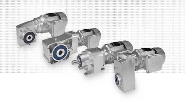
4) What type of gear reducer do you want? NORD Gear offers many different series of gearmotors, and there are many variables to consider. Here is a list of series that are available:
- UNICASE™ Helical In-Line Gearmotor: A Flexible, Reliable Solution

- NORDBLOC.1® Helical Inline Gear Unit: The Innovative Performer

- UNICASE™ CLINCHER™ Parallel Shaft Gearmotor: Compact and Powerful

- UNICASE™ Helical Bevel Gear Motor: Powerful and Proven

- Two-Stage Helical Bevel Gear Units: Performance and Design

- UNICASE™ Worm Gear Units: Quiet and Powerful

- FLEXBLOC® Worm Gear Unit: Modular and Flexible

- MINICASE™ Worm Gear Unit: Quiet, Smooth Operation

- Titan Belt Drives: Quiet and Robust

5) What type of input to the gear reducer would you like? NORD’s modular design allows for several different inputs to be added to their reducers such as:
- Integral Motor: An integral motor mounts directly into the gearbox, where the first stage gear of the gear reducer is attached directly to the motor shaft. The benefits of an integral units are; more compact design, lower cost, increased efficiency and they are more robust as there are fewer parts to wear out. The main downside is that it is more difficult to replace the motor if it fails down the road, as it was made specifically for that gear reducer. You will not find one locally, it will have to come from NORD.
- Solid Input Shaft: This type of reducer is designed to mount couplings, sheaves or sprockets, which transfer torque from the prime mover.
- NEMA C-Face Motor Adapter: NEMA C-face motor adapters allow for easy installation and removal of industry standard C-face motors. It consists of a coupling and an adapter housing that connects the motor housing to the gear reducer. The main benefit of this style is that it significantly simplifies the process of replacing the motor and it can accept any third-party motor with the same NEMA frame size. So, if your motor fails, you will be able to replace it much faster to get back up and running. The downsides are an added up-front cost, and it increases the overall length of the gearmotor.
- IEC Motor Adapter: IEC motor adapters also allow for easy installation and removal of industry standard IEC motors according to DIN 42677. This motor type is basically the same as the NEMA C-Face type mentioned above, but in metric dimensions and follows international standards.
- Servo Motor Adapter: Servo motor adapters are designed to handle the highly dynamic capabilities of servo motors. They have square mounting flanges and are available with either a keyed (SEP) or a keyless (SEK) coupling. They are only available on the helical in-line, Clincher™ shaft mount, helical-bevel and helical-worm units.
- Top Motor Mount Platform: Some applications require the motor to be mounted on top of the reducer with a belt drive connection from the motor to the reducer. The motor platforms are pre drilled and tapped to bolt on a standard NEMA footed motor. This input style has become much less common over the years as gearmotor technology has improved.
6) What position will the gearmotor be mounted in? This is a very important, and often overlooked specification when ordering a gear reducer. The mounting position determines how much oil the gear unit requires, in addition to the positioning of the oil drain, oil fill, and breather vent on the drive.
7) What type and size of output shaft do you want? There are a few different output shaft styles, and many different sizes available for NORD gear reducers. Some of the common styles are:
- Keyed Hollow Shaft: When using a standard keyed hollow shaft, your driven shaft will slide right through the gear unit and are secured with set screws. This is also known as a “direct drive” application. NORD’s standard keyed hollow shafts are made from SAE 1045 high carbon steel, feature standard keyway dimensions, and are available in both inch and metric designs in a wide range of bore diameters.
- Solid Keyed Shaft: When using a solid keyed shaft, you will have a shaft extending from the output of the gear reducer that you can mount a drive mechanism on, such as a pulley, sheave or sprocket. NORD’s standard solid keyed shafts are made from SAE 1045 high carbon steel, feature standard keyway dimensions, and are available in both inch and metric designs in a wide range of diameters.
- Shrink Disc: This is the same principal as the keyed hollow shaft design described above, but does not secure to the shaft using a keyway and set screws. Rather, the shrink disc creates a keyless, mechanical interference fit by converting locking screw tension into radial contact pressure on shaft and hub in effect “shrinking” it on to the customer supplied driven shaft. This results in a zero backlash and can accommodate higher torque than other mounting technologies and will never wear out. The shrink disc option also adds generous clearance for easy mounting and dismounting, as it won’t seize to the shaft, which is a common problem with the keyed hollow shaft design. This also allows for larger bore sizes compared to keyed hollow shafts.
- GRIPMAXX™ Keyless Bushing System: The NORD GRIPMAXX™ Keyless Bushing System uses the NORD shrink disc locking collar, an oversized gear reducer hollow bore, and a wide range of possible split-bushing inserts intended to accommodate a variety of imperial and metric bore sizes. This system is ideal for positioning or reversing applications as well as applications with frequent starts and stops. These bushings are also interchangeable, so the shaft size can be modified fairly simply.
8) Are there any other options or modifications you would like to explore? NORD gear reducers are highly customizable, and there are tons of additional options and modifications that can be selected. Below is a list of many of the available options.
Motor Housing
- Standard/Finned
- Smooth Surface (only available 0.5hp to 1.5hp)
Mounting Design
- Foot Mount

- Flange Mount

- Face Flange

- Foot Mount with Flange

- Foot Mount with Face Flange

- Screw Conveyor Package

Bearing Design
- Standard Bearings
- Heavy Duty Output Bearings - Heavy Duty Bearings increase the external load carrying capacity of the speed reducer. In addition to heavy duty bearings, a stronger shaft is provided to help increase overhung (radial) and thrust (axial) loading. The increased bearing capacity will also keep the speed reducer as small as possible by not having to select the next larger case size to handle the bearing loads.
- Extended Bearings - NORD offers three Extended Bearing options:
VL2 - SPREAD BEARING DESIGN: Reinforced output shaft bearings with increased bearing distance. This design is commonly used for shredders, mixers, overhead conveyors or applications requiring increased bearing capacities.
VL3 - SPREAD BEARING DESIGN WITH OIL SAFE DRY CAVITY: The dry cavity adds additional oil leak protective measures to the VL2 design.
VL4 - DRYWELL WITH HEAVY DUTY DROP BEARINGS: This option is available in our Clincher and Bevel units. This option provides the high capacity bearing design of the VL2/VL3 units with a drywell design.
Output Shaft Material
- Standard 1045 when standard bearings are selected or 4140 when heavy-duty bearings are selected.
- Stainless Steel AISI 304SS when standard bearings are selected or 17-4SS when heavy-duty bearings are selected.
Gearbox Sealing Options
- Standard Shaft Seal - For temperatures up to 125°C (250°F)
- FKM Seals (Viton) - For temperatures from -35°C to 200°C (-30°F to 400°F).
- Dual Output Seals - The QUADRILIP™ system has four components for sealing lubricant inside, and contaminants outside the speed reducer. The system includes a double lip seal, single lip seal and grease pack barrier.
- Dual FKM Output Seal (Viton) - The QUADRILIP™ system with FKM seals
Gearbox Breather Options
- Open Vent - Allows for air pressure differences between the inner space of the reducer and the atmosphere.
- Autovent™ - Prevents entry of foreign material, such as water, dust, corrosives, etc. and is perfect for washdown and dusty environments. It is a ball and spring check valve that opens at 2 psi during operation and closes tightly when the gearbox cools. This is a standard option on all NORD reducers.
- Stainless Steel Autovent™- Autovent™ but in stainless steel
- Filtered Vent - Similar to an open vent but with a filter to prevent foreign particle materials from entering the gearbox.
Other Gearbox Options
- Shaft Fixing Kit - To prevent the reducer from "walking out" of position. Includes all necessary parts to secure the shaft in the axial direction by using a tapped hole in the end of the mating male shaft.
- Shaft Cover (for hollow shaft, shrink disc, HD shrink disc, or Gripmaxx) - To guard from rotating hollow output shafts. It also protects the output shaft seals against dust and dirt particles and in some cases seals against moisture and dust.
- IP66 Hollow Shaft Cover - Protects against dust and water jets to completely seal the rotating hollow shaft from moisture and debris.
- Torque Arm - A compact, simple way to secure a shaft mounted reducer. It is bolted onto the reducer's B14 flange. The torque arm has a rubber bushing located at the fastening hole-end to act as a shock absorber to dampen out peak shock loads. Also available as bottom mount in some series.
- Backstop - To only allow rotation in one direction, it is installed internally and will hold the speed reducer's rated torque.
- Plug Threaded Holes - Plug all tapped holes and pin holes on the gear box with plastic plugs.
- Long Term Storage - Protects from moisture or corrosion by coating all unpainted surfaces with a dry, transparent, durable, waxy film. Once installation is necessary, this waxy film can be easily removed with a commercial de-greaser or petroleum solvent.
- Oil Sight Glass - Replaces the standard steel fill plug and consists of a sealed clear porthole centered in the middle of a brass plug and allows for quick oil level and color inspection.
- B5 Flange Pilot Removal - B5 flanges have a centering pilot machined onto the flange. In cases where there is not a matching counter bore or when the flange must sit flush to the mounting surface the centering pilot must be removed.
- Magnetic Drain Plug - To attract and hold ferrous metal particles that may circulate inside the reducer's lubrication system.
- Oil Expansion Chamber - To allow for expansion of the oil-air mix in the reducer that can occur during operation.
- Oil Cooler - An external device to cool the reducer's lubricating oil.
- Temperature Indicator Strip - Can be fastened to your gearbox to indicate its temperature. Generally used for maintenance and to easily allow detection of an overheating occurrence. Indicator set points will turn black when exposed to the related temperature.
Lubrication Type
- Mineral Oil with EP Additive, 32ºF to 104ºF (0ºC to 40ºC)
- Mineral Food Grade Oil, 23ºF to 104ºF (-5ºC to 40ºC)
- Synthetic Polyalphaolefin Oil with EP Additive, -31ºF to 140ºF (-35ºC to 60ºC)
- Food Grade Synthetic Polyalphaolefin Oil, -31ºF to 140ºF (-35ºC to 60ºC)
- Low Temp. Food Grade Synthetic Oil with EP Additive, -31ºF to 77ºF (-35ºC to 25ºC)
- No Oil
Motor Voltage
- 230/460
- 332/575
- 208/360
- 208-230/460
Motor Inverter Speed Range
- Standard Line Powered (Inverter Capable) - Premium Efficient (IE3) 0.16hp - 75hp motors are capable of 10:1 (60Hz - 6Hz) Constant Torque Turndown and Standard Efficient (IE1) 0.16hp - 40hp motors are rated for 5:1 (60Hz - 12Hz) Constant Torque Turndown.
- 1000+:1, (60-0Hz) Constant Torque - Motor is rated for 1000:1 Constant torque (60Hz - 0Hz) VFD service. External cooling fan is supplied for adequate cooling at low operating frequencies.
- Line Powered Only (not inverter rated)
Motor Enclosure
- IP55 - Dust protected and protected against low pressure water jets from all directions.
- IP66 - Dust tight and protection against low-pressure water jets and wash down environments.
- IP69K - Dust Proof and protected against close-range high pressure, high temperature spray downs. Water temperatures up to 80°C (176°F). Smooth Surface Motor must be selected.
Motor Cooling
- TEFC – Totally Enclosed Fan Cooled
- TEBC – Totally Enclosed Blower Cooled
- TENV – Totally Enclosed Non-Ventilated
Powered by NORD AC Drive
- No
- Decentralized Drive - VFD to be mounted directly on motor or include kit for mounting on wall.
- Cabinet Mounted Drive - IP20 Drive for inside control panel.
Motor Thermal Protection
- None
- Thermistor - In connection with a tripping device, this is employed to monitor the motor temperature. NORD does not provide the external tripping device with the TF thermistor option; you must request this device separately.
- Thermostat - Can be wired into the motor control circuit without a separate control module or tripping device. Normally closed and auto-resetting.
Motor Options
- IP55 Brake - Spring-set when power is removed from the brake circuit (power-off). The brake coil utilizes a DC voltage supplied through a rectified power source.
- Encoder - Used as speed or position feedback devices for use with AC drives, motion controllers or PLC's.
- Temperature Indicator Strip - Can be fastened to your motor to indicate its temperature. Generally used for maintenance and to easily allow detection of an overheating occurrence. Indicator set points will turn black when exposed to the related temperature.
- High Inertia Cast Iron Fan - Used as a mechanical soft start and/or soft stop by adding inertia to the motor. Can also be used for a flywheel effect to store mechanical energy. This fan will replace the standard plastic motor fan.
- 2nd Shaft Extension - A second shaft extension on the fan side of the motor that protrudes through the fan cover. This extension can be used as a power take-off or to mount customer supplied devices.
- Hand Wheel - Can be used for manual operation during power outages or for machine positioning setup. It is mounted on the second shaft extension.
- Canopy Drip Cover - For wet or dirty installations where the fan end of the motor is mounted up, this prevents water or debris from falling into the motor's fan guard.
- Double Fan Cover - For wet or dirty installations where the fan end of the motor is mounted up, provides protection against falling or wind-blown water, snow, dirt or debris from entering the back of the motor.
- Anti-Condensation Heater - To heat up the windings when the motor is not operating. This will prevent moisture from condensing inside the motor. Available in 115V, 230V and 460V.
- Condensation Drain Holes (open or closed) - These drain holes are placed in the motor endbells at the lowest possible point. They allow for condensation accumulation in the motor to drain after the closing plugs are removed.
- Terminal Box Sealed with Resin - A flexible, electrically safe resin to ensure that contaminants, water, and moisture cannot pass through the terminal box into the stator body.
- Small Terminal Box - A smaller, one-piece terminal design. This option is valid for standard motors 0.16 - 10 hp and is not available for brake motors.
- Fluoro Rubber (FKM) Motor Seals - For temperatures from -35°C to 200°C (-30°F to 400°F).
- Aluminum Fan - Often used in very hot ambient environments or in potentially explosive areas in place of polymer fans that can store static electricity.
- Class H Motor Insulation - Beneficial in some severe applications. The insulation is advantageous for increased ambient temperature installations above 40˚C (104˚F), increased elevation installations above 3300 ft (1000 m), applications with large numbers of starts per hour and lower operating frequency when used with frequency inverter systems.
- Additional Insulation - To provide additional electrical protection in extremely wet or corrosive environments.
- Epoxy Dipped Windings - To improve moisture protection for extremely wet environments.
Terminal Box Position

Conduit Entry Location

Paint Coating
- No Paint
- Primed Only
- Basic (Standard Paint): For Indoor Installation
- Basic +: For Indoor Installation + clear coat
- NSD2: Indoor Installation and protected outdoors
- NSD2+: Indoor Installation and protected outdoors + clear coat
- NSD3: For outdoor installation with low environmental contamination
- NSD3+: For outdoor installation with low environmental contamination + clear coat
- NSDC3: For normal chemical contamination
- NSDF3: For food packaging areas
- NSDF3+: For food packaging areas + clear coat
- NSD4: For outdoor installation with moderate environmental contamination
- NSD4+: For outdoor installation with moderate environmental contamination + clear coat
- NSD5: For outdoor installation with high environmental contamination
- NSD5+: For outdoor installation with high environmental contamination + clear coat
Paint Color
- Standard is Stainless Steel Gray
- RAL 9003 Signal White (requires NSD2 or higher)
- RAL 3002 Carmine Red
- RAL 3011 Brown Red
- RAL 5005 Signal Blue
- RAL 5010 Blue
- RAL 9005 Jet Black
9) Now it is time to double check some important factors of the selected unit for your application.
- Overhung Loads: Also known as a radial load, an overhung load is a force that is applied to the output shaft at right-angles, beyond the outermost bearing of the reducer. Pulleys, sheaves and sprockets cause an overhung load. It is best to apply your overhung load is best to be installed at the midpoint of the shaft extension and without thrust loads. CLICK HERE for a detailed explanation of how to calculate an overhung load, and the capabilities of each reducer series and size.
- Thrust Loads: Also known as an axial load, a thrust load is a force that is directed towards or away from the gearbox along the axis of the shaft. Thust loads are a little more difficult to calculate; if your application has thrust loads involved, especially when in combination with overhung loads, it would be best to contact us or an engineer at NORD to evaluate your application details.
- NEMA C-face Motor Weight Limits: When mounting a motor to a speed reducer with a C-Face motor adapter, it is important to consider the weight of the motor. Below is a table that includes the maximum motor weight that a NORD NEMA motor adapter can support. If your motor exceeds the weight limit of the adapter, be sure to support the weight of your motor externally.
| Motor Frame | 56C | 143TC | 145TC | 182TC | 184TC | 210TC |
| Max Weight (lb) | 66 | 88 | 110 | 130 | 175 | 220 |
| Motor Frame | 250TC | 280TC | 324TC | 326TC | 365TC | |
| Max Weight (lb) | 450 | 550 | 770 | 1100 | 1550 |
As you may have gathered, selecting the perfect gearmotor for your application can be a daunting task, but NORD Gear has made it easier with their wide range of products and modularity. Whether you are looking for a replacement or a new application, Power Motion & Industrial Supplies is here to help. By answering the above questions, we can determine the right gearmotor for your needs. And if you have any trouble, feel free to reach out to us! With millions of possible configurations available, it is essential to work with a knowledgeable distributor like us to configure the perfect gearmotor for your application. We encourage you to contact us for any assistance, and we look forward to helping you find the perfect gearmotor!

Tags:
SK02, SK03, SK11E, SK12, SK13, SK21E, SK22, SK23, SK31E, SK32, SK33N, SK41E, SK42, SK43, SK51E, SK52, SK53, SK62, SK63, SK72, SK73, SK82, SK83, SK92, SK93, SK102, SK103
SK072.1, SK172.1, SK372.1, SK373.1, SK572.1, SK573.1, SK672.1, SK673.1, SK772.1, SK773.1, SK872.1, SK873.1, SK972.1, SK973.1
SK1282, SK2282, SK2382, SK3282, SK3382, SK4282, SK4382, SK5282, SK5382, SKSK6282, SK6382, SK7282, SK7382, SK8282, SK8382, SK9282, SK9382, SK10382.1, SK11382.1, SK12382
SK9012.1, SK9013.1, SK9016.1, SK9017.1, SK9022.1, SK9023.1, SK9032.1, SK9033.1, SK9042.1, SK9043.1, SK9052.1, SK9053.1, SK9072.1, SK9082.1, SK9086.1, SK9092.1, SK9096.1, SK92072.1, SK92172.1, SK92372.1, SK92672.1, SK92772.1, SK93072.1, SK93172.1, SK93372.1, SK93672.1, SK93772.1
SK02050, SK13050, SK12063, SK13063, SK12080, SK13080, SK32100, SK33100, SK42125, SK43125
SK1SI31, SK1SMI31, SK1SI40, SK1SMI40, SK1SI50, SK1SMI50, SK1SI63, SK1SMI63, SK1SI75, SK1SMI75
SK7207, SK7307, SK8207, SK8307, SK9207, SK9307, SK10207, SK10307, SK11207, SK11307, SK12207, SK12307, SK13207, SK13307, KS14207, SK14307, SK15207, SK15307
SK7407, SK7507, SK8407, SK8507, SK9407, SK9507, SK10407, SK10507, SK11407, SK11507, SK12407, SK12507, SK13407, SK13507, SK14407, SK14507, SK15407, SK15507
SK63S/4, SK63L/4, SK71S/4, SK71L/4, SK80S/4, SK80L/4, SK90S/4, SK90L/4, SK100L/4, SK100LA/4, SK112M/4, SK132S/4, SK132M/4, SK132MA/4, SK160M/4, SK160L/4, SK180MX/4, SK180LX/4, SK200LX/4
SK63S/2, SK63L/2, SK71S/2, SK71L/2, SK80S/2, SK80L/2, SK90S/2, SK90L/2, SK100L/2, SK112M/2, SK132S/2, SK132SA/2, SK132M/2
SK63S/6, SK63L/6, SK71S/6, SK71L/6, SK80S/6, SK80L/6, SK90S/6, SK90L/6, SK100L/6, SK112M/6, SK132S/6, SK132M/6, SK132MA/6
SK63S/4-2, SK63L/4-2, SK71S/4-2, SK71L/4-2, SK80S/4-2, SK80L/4-2, SK90S/4-2, SK90L/4-2, SK100L/4-2, SK100LA/4-2, SK112M/4-2, SK112MA/4-2, SK132S/4-2, SK132M/4-2, SK132MA/4-2, SK160M/4-2, SK160L/4-2
SK71S/8-2WU, SK71L/8-2WU, SK80S/8-2WU, SK80L/8-2WU, SK90S/8-2WU, SK90L/8-2WU, SK100L/8-2WU, SK100LA/8-2WU, SK112M/8-2WU, SK132S/8-2WU, SK132M/8-2WU
SK71S/8-2, SK71L/8-2, SK80S/8-2, SK80L/8-2, SK90S/8-2, SK90L/8-2, SK100L/8-2, SK100LA/8-2, SK112M/8-2, SK132S/8-2, SK132M/8-2
SK63L/4EHB1, SK63LA/4EHB1, SK71L/4EHB1, SK71LA/4EHB1, SK80L/4EHB1, SK80LA/4EHB1, SK90L/4EHB1, SK90LB/4EHB1
SK63L/4EAR1, SK63LA/4EAR1, SK71L/4EAR1, SK71LA/4EAR1, SK80L/4EAR1, SK80LA/4EAR1, SK90L/4EAR1, SK90LB/4EAR1
SK63L/4EST, SK63L/4EST, SK71S/4EST, SK71L/4EST, SK80S/4EST, SK80L/4EST, SK90S/4EST, SK90L/4EST
SK63LA/4ECR, SK71L/4ECR, SK71LA/4ECR, SK80L/4ECR, SK80LA/4ECR, SK90L/4ECR, SK90LB/4ECR, SK90LX/4ECR
SK63S/4EST, SK63L/4EST, SK71S/4EST, SK71L/4EST, SK80S/4EST, SK80L/4EST, SK90S/4EST, SK90L/4EST
SK80SH/4, SK80LH/4, SK90SH/4, SK90LH/4, SK100LH/4, SK100AH/4, SK112MH/4, SK132SH/4, SK132MH/4, SK132LH/4, SK160SH/4, SK160MH/4, SK160LH/4, SK180MH/4, SK180LH/4, SK200XH/4, SK225SH/4, SK225MH/4, SK225WH/4
SK80SH/2, SK80LH/2, SK90SH/2, SK90LH/2, SK100LH/2, SK112MH/2, SK132SH/2, SK132RH/2
SK80LP/4, SK90SP/4, SK90LP/4, SK100LP/4, SK100AP/4, SK112MP/4, SK132SP/4, SK132MP/4, SK160SP/4, SK160MP/4, SK160LP/4, SK180MP/4, SK180LP/4, SK225RP/4, SK225SP/4, SK225MP/4, SK250WP/4
SK80T1/4, SK80T1/4HM, SK90T1/4, SK90T3/4, SK90T3/4HM, SK100T2/4, SK100T5/4, SK100T5/4HM
SK63S/42D, SK63L/42D, SK71S/42D, SK71L/42D, SK80S/42D, SK80L/42D, SK90S/42D, SK90L/42D, SK100L/42D, SK100LA/42D, SK112M/42D, SK132S/42D, SK132M/42D, SK132MA/42D
SK63S/43D, SK63L/43D, SK71S/43D, SK71L/43D, SK80S/43D, SK80L/43D, SK90S/43D, SK90L/43D, SK100L/43D, SK100LA/43D, SK112M/43D, SK132S/43D, SK132M/43D, SK132MA/43D
SK80SH/42D, SK80LH/42D, SK90SH/42D, SK90LH/42D, SK100LH/42D, SK100AH/42D, SK112MH/42D, SK132SH/42D, SK132MH/42D, SK132LH/42D, SK160MH/42D, SK160LH/42D, SK180MH/42D, SK180LH/42D
SK80SH/43D, SK80LH/43D, SK90SH/43D, SK90LH/43D, SK100LH/43D, SK100AH/43D, SK112MH/43D, SK132SH/43D, SK132MH/43D, SK132LH/43D, SK160MH/43D, SK160LH/43D, SK180MH/43D, SK180LH/43D
Leave a comment